KFS guide system
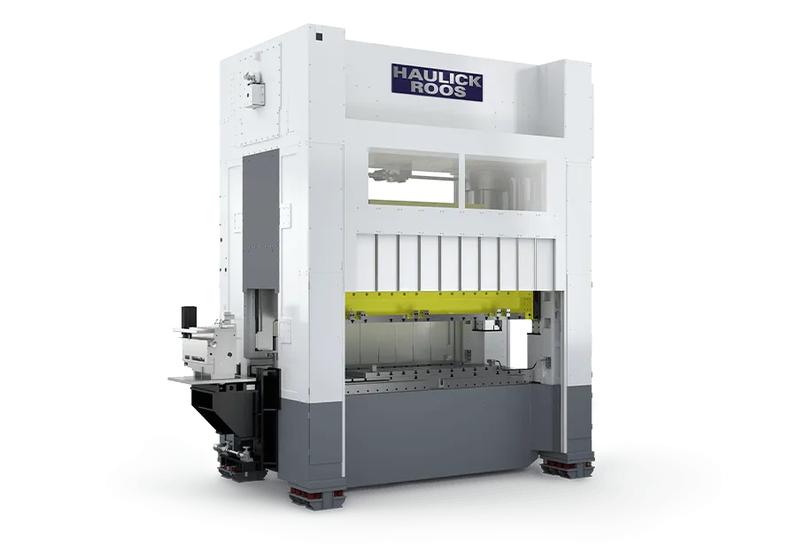
Additional plunger guides in the press frame combine with the slide guide, raising tilt rigidity left to right and front to back; direct con-rod drive without intermediate joints.
Since 198343 years serving Turkish industry

Precision stamping and forming presses
Precision stamping and forming press with KFS guide system and optional FSD servo drive
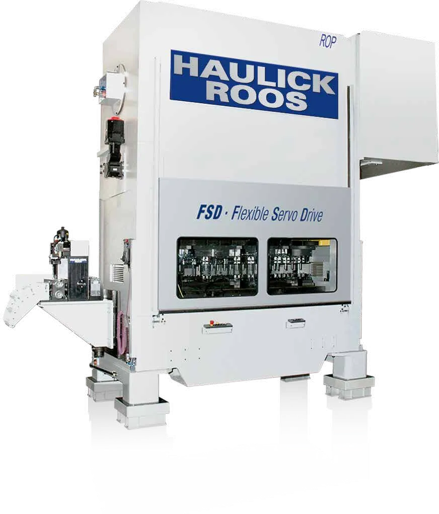
ⓘ Manufacturer data; Haulick + Roos ROP brochure and product page. Values may change and vary; not binding on Boztaş.
Additional plunger guides in the press frame combine with the slide guide, raising tilt rigidity left to right and front to back; direct con-rod drive without intermediate joints.
Monoblock frame in nodular cast iron (GJS) with a closed oil circuit; the bolster serves as the oil tank; slide guided to below the strip line in preloaded rolling-bearing bushes.
Freely programmable slide speed; pre-programmed profiles for drawing, bending, coining and cutting; creep speed at full press force and handwheel die try-out.
Tool space 1,000 or 1,250 mm; stroke 12–60 mm; 30–400 1/min (FSD 1–400); bolster depth 730 mm; 10,100–11,400 kg
Suited to: 500 and 630 kN; tool space up to 1,250 mm
Tool space 1,000, 1,250 or 1,600 mm; stroke 11–120 mm; 30–400 to 30–300 1/min (FSD 1–300); bolster depth 890 mm; 16,100–19,900 kg
Suited to: Tool space up to 1,600 mm
Tool space 1,250, 1,600 or 2,000 mm; stroke 12–120 mm; 30–300 1/min (FSD 1–260); bolster depth 1,100 mm; 25,800–35,400 kg
Suited to: Tool space up to 2,000 mm, 1,600 kN
Slide speed slowed from any position over any stroke section; pre-programmed motion profiles for drawing, bending, coining and cutting; creep speed at full press force and handwheel try-out; switched off, the press runs like a classic eccentric press at higher output
Suited to: Parts needing variable forming speed, and die try-out
Fixed-stroke design; no doors or panels in the tool area; vibration-sensitive components (encoder, motor etc.) on damped mounts; drive, feed and other units decoupled from the press; available on ROS and ROP with a close-fitting, safeguarded sound enclosure
Suited to: Parts with high cutting-shock load such as washers, chain link plates and rotor-stator laminations
| Feature | ROP 500 | ROP 630 | ROP 800 | ROP 1000 | ROP 1250 | ROP 1600 |
|---|---|---|---|---|---|---|
| Press | ||||||
| Nominal press force | 500 kN | 630 kN | 800 kN | 1,000 kN | 1,250 kN | 1,600 kN |
| Tool space, left to right (options) | 1,000 / 1,250 mm | 1,000 / 1,250 mm | 1,000 / 1,250 / 1,600 mm | 1,000 / 1,250 / 1,600 mm | 1,250 / 1,600 / 2,000 mm | 1,250 / 1,600 / 2,000 mm |
| Slide stroke, fixed (max.) | 60 mm | 60 mm | 120 mm | 120 mm | 120 mm | 120 mm |
| Slide stroke, adjustable | 12–60 mm | 12–60 mm | 11–120 mm | 11–120 mm | 12–120 mm | 12–120 mm |
| Slide adjustment | 60 mm | 60 mm | 80 mm | 80 mm | 100 mm | 100 mm |
| Speed | ||||||
| Stroke rate, flywheel drive | 30–400 1/min | 30–400 1/min | 30–400 / 30–350 / 30–300 1/min | 30–400 / 30–350 / 30–300 1/min | 30–300 1/min | 30–300 1/min |
| Stroke rate, FSD servo drive | 1–400 1/min | 1–400 1/min | 1–300 1/min | 1–300 1/min | 1–260 1/min | 1–260 1/min |
| Bolster and tool space | ||||||
| Max. die height (stroke down, adjustment up) | 320 mm | 320 mm | 360 mm | 360 mm | 420 mm | 420 mm |
| Bolster area (length × depth) | 1,000 × 730 / 1,250 × 730 mm | 1,000 × 730 / 1,250 × 730 mm | 1,000 × 890 / 1,250 × 890 / 1,600 × 890 mm | 1,000 × 890 / 1,250 × 890 / 1,600 × 890 mm | 1,250 × 1,100 / 1,600 × 1,100 / 2,000 × 1,100 mm | 1,250 × 1,100 / 1,600 × 1,100 / 2,000 × 1,100 mm |
| Slide clamping area (length × depth) | 1,000 × 450 / 1,250 × 450 mm | 1,000 × 450 / 1,250 × 450 mm | 1,000 × 550 / 1,250 × 550 / 1,600 × 550 mm | 1,000 × 550 / 1,250 × 550 / 1,600 × 550 mm | 1,250 × 700 / 1,600 × 700 / 2,000 × 700 mm | 1,250 × 700 / 1,600 × 700 / 2,000 × 700 mm |
| Passage between uprights | 310 mm | 310 mm | 415 mm | 415 mm | 505 mm | 505 mm |
| Bolster opening (length × depth) | 910 × 140 / 1,160 × 140 mm | 910 × 140 / 1,160 × 140 mm | 910 × 200 / 1,160 × 200 / 1,510 × 200 mm | 910 × 200 / 1,160 × 200 / 1,510 × 200 mm | 1,160 × 300 / 1,510 × 300 / 1,910 × 300 mm | 1,160 × 300 / 1,510 × 300 / 1,910 × 300 mm |
| Opening with split bolster plate, adjustable in depth | 40–140 mm | 40–140 mm | 60–220 mm | 60–220 mm | 120–300 mm | 120–300 mm |
| Bolster plate height | 100 mm | 100 mm | 125 mm | 125 mm | 150 mm | 150 mm |
| Design | ||||||
| Press frame | Monoblock, nodular cast iron (GJS); bolster serves as the oil tank | Monoblock, nodular cast iron (GJS); bolster serves as the oil tank | Monoblock, nodular cast iron (GJS); bolster serves as the oil tank | Monoblock, nodular cast iron (GJS); bolster serves as the oil tank | Monoblock, nodular cast iron (GJS); bolster serves as the oil tank | Monoblock, nodular cast iron (GJS); bolster serves as the oil tank |
| Drive train | Double connecting rod, eccentric shaft on 4 rolling bearings, full-complement roller con-rod bearings | Double connecting rod, eccentric shaft on 4 rolling bearings, full-complement roller con-rod bearings | Double connecting rod, eccentric shaft on 4 rolling bearings, full-complement roller con-rod bearings | Double connecting rod, eccentric shaft on 4 rolling bearings, full-complement roller con-rod bearings | Double connecting rod, eccentric shaft on 4 rolling bearings, full-complement roller con-rod bearings | Double connecting rod, eccentric shaft on 4 rolling bearings, full-complement roller con-rod bearings |
| Guide system | KFS (slide guide + plunger guides in the frame); slide guided to below the strip line in backlash-free, preloaded rolling-bearing bushes | KFS (slide guide + plunger guides in the frame); slide guided to below the strip line in backlash-free, preloaded rolling-bearing bushes | KFS (slide guide + plunger guides in the frame); slide guided to below the strip line in backlash-free, preloaded rolling-bearing bushes | KFS (slide guide + plunger guides in the frame); slide guided to below the strip line in backlash-free, preloaded rolling-bearing bushes | KFS (slide guide + plunger guides in the frame); slide guided to below the strip line in backlash-free, preloaded rolling-bearing bushes | KFS (slide guide + plunger guides in the frame); slide guided to below the strip line in backlash-free, preloaded rolling-bearing bushes |
| Mass balancing | Rotating masses | Rotating masses | Rotating masses | Rotating masses | Rotating masses | Rotating masses |
| Slide and stroke adjustment | Electric-motor slide adjustment; quick tool release and fine adjustment during operation, automatic stroke adjustment optional | Electric-motor slide adjustment; quick tool release and fine adjustment during operation, automatic stroke adjustment optional | Electric-motor slide adjustment; quick tool release and fine adjustment during operation, automatic stroke adjustment optional | Electric-motor slide adjustment; quick tool release and fine adjustment during operation, automatic stroke adjustment optional | Electric-motor slide adjustment; quick tool release and fine adjustment during operation, automatic stroke adjustment optional | Electric-motor slide adjustment; quick tool release and fine adjustment during operation, automatic stroke adjustment optional |
| Control | ||||||
| Control | Modular PC control with colour touch display; integrated process monitoring | Modular PC control with colour touch display; integrated process monitoring | Modular PC control with colour touch display; integrated process monitoring | Modular PC control with colour touch display; integrated process monitoring | Modular PC control with colour touch display; integrated process monitoring | Modular PC control with colour touch display; integrated process monitoring |
| Connections | ||||||
| Required air pressure | 6 bar | 6 bar | 6 bar | 6 bar | 6 bar | 6 bar |
| Dimensions and weight | ||||||
| Weight without feed (approx.) | 10,100 / 11,200 kg | 10,300 / 11,400 kg | 16,100 / 17,800 / 19,500 kg | 16,500 / 18,200 / 19,900 kg | 25,800 / 30,700 / 34,400 kg | 27,400 / 32,000 / 35,400 kg |
Manufacturer data; Haulick + Roos ROP brochure and product page. Multiple values are listed left to right by tool-space option (e.g. ROP 800: 1,000 / 1,250 / 1,600 mm). The FSD stroke rate depends on the FSD variant. Model name: ROP 1000-1600 = 1,000 kN, 1,600 mm tool space. Technical changes reserved by the manufacturer.
Technical data is taken from information published by the manufacturer. The manufacturer may change it without notice, and values may vary with the model and the machine configuration. The data is for information only and is not binding on Boztaş; binding values are stated only in a written quotation.
Related industries: AutomotiveMachine BuildingElectricalElectronics and ConnectorsDomestic AppliancesMedical
With FSD the slide speed is slowed from any position over any stroke section, independently of the stroke length: low speed in the forming zone, high speed elsewhere. With FSD switched off, the press runs like a classic eccentric press at higher output. In this series the FSD stroke rate ranges from 1–400 1/min (500 and 630 kN) to 1–260 1/min (1,250 and 1,600 kN).
At the same size the ROS reaches higher stroke rates (e.g. 1,000 kN with 1,000 mm tool space: ROS 30–900, ROP 30–400 1/min). The ROP offers an optional FSD servo drive; the ROS brochure lists no servo drive.
500 and 630 kN: 1,000 × 730 or 1,250 × 730 mm; 800 and 1,000 kN: 1,000, 1,250 or 1,600 × 890 mm; 1,250 and 1,600 kN: 1,250, 1,600 or 2,000 × 1,100 mm.
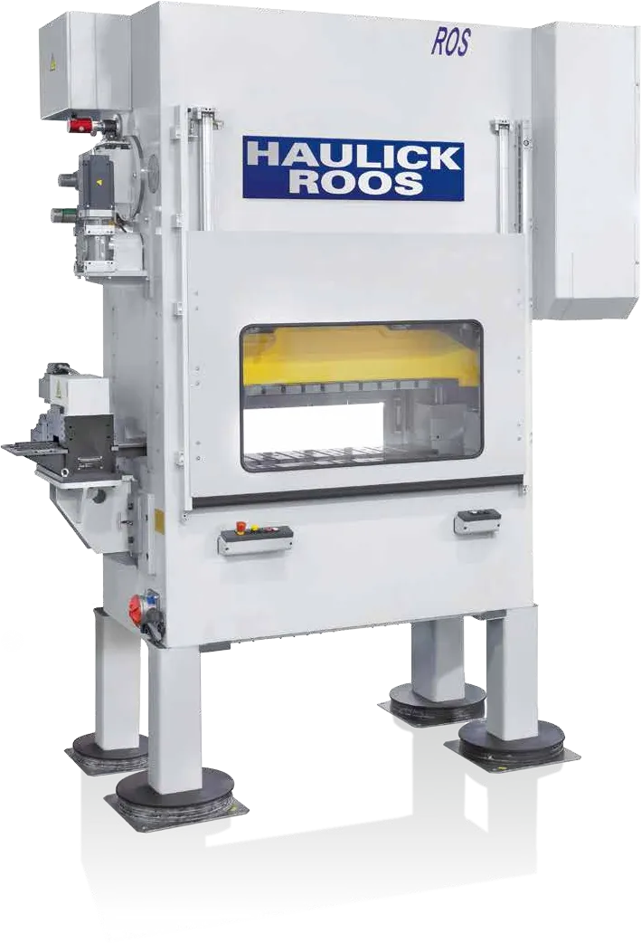 Haulick + Roos ROS 500–1,600 kN Precision high-speed stamping press with monoblock cast frame and full mass balancing 500–1,600 kN≤ 1,050 1/min1,000–2,000 mm Technical data
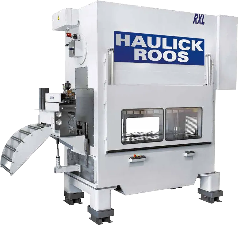 Haulick + Roos RXLneo 250–1,000 kN Precision stamping and forming press, the alternative to the ROP from 250 to 1,000 kN 250–1,000 kN760–1,600 mm Technical data
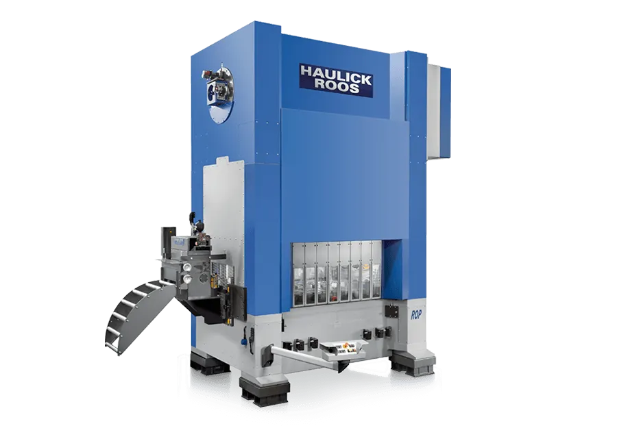 Haulick + Roos ROP 2,000–3,150 kN Large precision stamping and forming press with three-part cast frame, optional planetary gear and FSD servo drive 2,000–3,150 kN≤ 250 1/min1,600–3,000 mm Technical data
 Haulick + Roos ROP 4,000–5,000 kN Large precision stamping and forming press with up to 3,500 mm tool space, planetary gear or FSD servo drive 4,000–5,000 kN≤ 100 1/min2,500–3,500 mm Technical data